

 Send Email

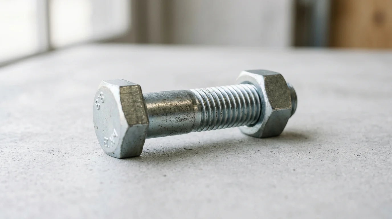
A hex bolt may look simple, but in a loaded joint it carries consequences measured in safety, uptime, and liability. The difference between a compliant fastener and a questionable one is rarely visible on the surface; it is proven through controlled testing, documented standards, and verified mechanical performance. This article explains how recognized ASTM, ISO, and SAE requirements help confirm strength, proof load, material quality, coatings, and markings. It also shows why procurement teams and engineers should treat testing data as a practical risk-control tool, especially when torque accuracy, installation reliability, and long-term assembly performance matter.
Why Hex Bolt Testing Standards Matter
In industrial manufacturing, construction, and heavy machinery, the structural integrity of an assembly relies heavily on the quality of its hardware. Testing standards for these components are not merely bureaucratic hurdles; they are fundamental engineering protocols designed to prevent catastrophic failures. Establishing a rigorous testing framework ensures that each component can endure the specific mechanical and environmental stresses it will face in the field.
The global supply chain provides access to a vast array of hex bolts, making it essential to differentiate between compliant, high-quality parts and substandard alternatives. Relying on visual inspection alone is insufficient, as metallurgical flaws, improper heat treatment, and inadequate coatings are invisible to the naked eye. By adhering to the latest editions of internationally recognized testing standards from organizations such as ASTM, ISO, and SAE, engineers and procurement teams establish a baseline of reliability that safeguards both personnel and capital investments.
How Test Results Reduce Installation Failures
Installation failures, such as thread stripping, head snapping, or galling, frequently occur when parts fail to meet specified mechanical properties. Testing results provide the empirical data necessary to establish accurate torque-tension relationships. When an assembly line operates without verified material data, the risk of over-tightening or under-tightening increases significantly, leading to uneven load distribution across the joint.
Properly tested hardware can substantially reduce installation-related failures. Engineers typically calculate target preloads at 75% to 80% of a verified proof load, though this exact percentage is highly dependent on the specific standard, joint design, and friction coefficients. If a batch has not been tested to confirm this proof load, applying the calculated torque may cause the metal to yield permanently during installation. Comprehensive testing ensures that the material behaves predictably within its elastic limit, allowing for secure clamping forces without compromising structural integrity.
Commercial Risks of Poor Specifications
The commercial repercussions of utilizing unverified components extend far beyond the initial purchase price. Poorly specified or untested bolts introduce severe financial liabilities, including product recalls, warranty claims, and extensive equipment downtime. When a critical joint fails in service, the root cause analysis often points back to a discrepancy between the assumed mechanical properties and the actual performance of the part.
Consider the economic disparity: a single non-compliant bolt may cost mere cents to procure, but its failure in a heavy industrial application can trigger equipment downtime costing thousands of dollars per hour, excluding potential safety liabilities and secondary damage to the machinery. Furthermore, utilizing components that lack proper testing documentation can void manufacturer warranties and violate industry-specific safety regulations, exposing companies to significant legal and commercial risks. Rigorous specification and adherence to testing standards function as a highly cost-effective insurance policy against these disproportionate downstream costs.
Hex Bolt Grades, Materials, and Markings

The mechanical capabilities of a bolt are dictated by its grade, material composition, and manufacturing processes. To navigate the complex landscape of industrial hardware, professionals must possess a thorough understanding of how these classifications dictate performance limits and the specific tests required to verify them. International standards provide a universal language for these specifications, ensuring that a component manufactured in one region performs identically to one produced elsewhere.
Grades, Property Classes, and Material Types
Component strength is categorized through specific grading systems, most notably SAE J429 for inch-based hardware and ISO 898-1 for metric equivalents. SAE grades, such as Grade 2, 5, and 8, indicate ascending levels of tensile and yield strength achieved through varying carbon content and heat treatment processes. Conversely, the metric system utilizes property classes like 8.8, 10.9, and 12.9. In this system, the first digit represents one-hundredth of the nominal tensile strength in megapascals (MPa), while the second digit represents the ratio of yield strength to tensile strength. It is important to note that mechanical properties are often size-dependent; standards specify different minimum values depending on the nominal diameter.
Material selection is inextricably linked to these grades. Lower property classes typically utilize low or medium carbon steels, whereas high-strength applications demand medium carbon alloy steels that have been quenched and tempered. For specialized environments, austenitic stainless steels (such as A2 and A4) are specified for their corrosion resistance, though they exhibit different mechanical behaviors, such as strain hardening, compared to standard carbon steel variants.
Markings, Dimensions, Threads, and Coatings
Standardized markings stamped onto the head serve as a critical field verification tool, indicating the manufacturer's identification and the specific grade or property class. Absence of these markings on high-strength hardware is a direct violation of international standards and a strong indicator of counterfeit or non-compliant parts. Beyond markings, dimensional tolerances are strictly governed by standards such as ASME B18.2.1 and ISO 4014, ensuring proper tool engagement and load distribution under the head.
Thread fits and tolerances are equally critical. Metric threads are often specified with a 6g tolerance class, while inch threads typically use a 2A fit, ensuring smooth assembly without excessive play. Coatings add another layer of specification; electroplated zinc, hot-dip galvanization, and zinc-flake coatings (like Geomet or Dacromet) are applied to combat corrosion. The thickness of these coatings must be carefully managed—for instance, standard electroplating typically adds 5 to 8 micrometers of thickness, though this range is strictly dependent on the specified standard and nominal diameter. This added material must be accounted for to prevent thread interference during assembly.
The table below illustrates baseline properties for common smaller diameter ranges (e.g., up to 1/2 inch or M16). It is crucial to note that mechanical properties are highly diameter-dependent; actual minimums and hardness ranges vary strictly by nominal diameter and standard.
| Specification System | Common Designation | Min. Tensile Strength | Min. Yield Strength | Core Hardness Range |
|---|---|---|---|---|
| SAE J429 (Inch) | Grade 5 | 120,000 psi | 92,000 psi | C25 - C34 (Rockwell) |
| SAE J429 (Inch) | Grade 8 | 150,000 psi | 130,000 psi | C33 - C39 (Rockwell) |
| ISO 898-1 (Metric) | Class 8.8 | 800 MPa | 640 MPa | C22 - C32 (Rockwell) |
| ISO 898-1 (Metric) | Class 10.9 | 1040 MPa | 940 MPa | C32 - C39 (Rockwell) |
When to Specify Standard Requirements
Engineers should specify standard requirements whenever an application involves dynamic loading, high pressures, or extreme temperatures. Relying on generic hardware is only acceptable for non-structural, low-stress applications where failure poses no safety or operational risk. As a general rule, structural, safety-critical, or dynamically loaded joints generally require standard-compliant components regardless of a specific preload threshold.
Furthermore, environmental extremes dictate strict adherence to specific standards. For instance, applications operating at temperatures exceeding 150°C require the specification of high-temperature alloys, such as ASTM A193 Grade B7, which are explicitly tested to maintain their mechanical integrity under thermal stress. Specifying standard requirements ensures that the procured hex bolts have undergone the precise heat treatments and testing regimens necessary to survive their intended operational lifespan.
Key Hex Bolt Testing Methods
Verifying that a part meets its designated grade requires a combination of destructive and non-destructive testing (NDT) methodologies. These tests are conducted in accredited laboratories utilizing calibrated equipment to measure how the material responds to extreme forces, chemical exposure, and metallurgical analysis. Understanding these testing methods allows procurement and engineering teams to interpret test reports accurately.
Tensile Strength, Proof Load, Yield Strength, and Hardness
The mechanical backbone of hardware testing revolves around tensile strength, proof load, yield strength, and hardness. Axial and wedge tensile testing involves pulling the sample apart until fracture occurs, measuring the maximum load it can withstand (Ultimate Tensile Strength). Wedge testing specifically introduces an angled block beneath the bolt head—typically between 4 to 10 degrees depending on the size—to induce bending stress, ensuring the head-to-shank transition is ductile and free of manufacturing defects.
Proof load testing is a critical mechanical test. While it does not destroy compliant parts, it will permanently deform any piece that fails to meet specifications. It involves subjecting the part to a specific axial load, which is usually defined as a strict percentage of the standard's specified proof stress rather than a loosely estimated yield strength. The exact load and required hold time are defined by the applicable product standard; for instance, ISO 898-1 and ASTM F606 specify different durations (e.g., 10 or 15 seconds) and load percentages depending on the size and specification. Upon release of the load, the part is measured; it must exhibit zero permanent elongation (within a strict tolerance).
Hardness testing, utilizing Rockwell or Vickers scales, provides a rapid estimation of tensile strength and verifies the uniformity of the heat treatment process across the production lot. However, because it leaves minor surface indentations, it is not fully non-destructive. For true non-destructive testing (NDT), methods such as magnetic-particle or ultrasonic testing are frequently employed to detect internal or surface flaws without damaging the component.
Chemical, Metallurgical, and Coating Tests
While mechanical tests confirm strength, chemical and metallurgical tests verify the underlying material composition and structural integrity. Optical emission spectroscopy is utilized to analyze the chemical makeup of the steel, ensuring the correct percentages of carbon, manganese, chromium, and other alloying elements are present. Metallurgical analysis involves sectioning the sample, polishing, etching, and examining the microstructure under high magnification to detect flaws such as micro-cracks, inclusions, or improper grain structures.
Decarburization testing is a specific metallurgical check that measures the loss of carbon at the surface of the threads, a condition that can significantly weaken thread strength and lead to stripping. Coating tests primarily focus on corrosion resistance. The most common is the salt spray test (e.g., ASTM B117), where parts are exposed to a saline mist in a controlled chamber. Depending on the coating specification, acceptance criteria may demand anywhere from 96 hours to over 1000 hours of continuous exposure before the first appearance of red rust. It is important to note, however, that ASTM B117 results are coating-specific and do not always correlate directly with field service life or long-term corrosion performance.
Comparison of Test Purposes and Acceptance Criteria
Different tests serve distinct purposes, and their acceptance criteria are strictly defined by the latest editions of governing standards. Mechanical tests ensure load-bearing capacity, chemical tests guarantee material authenticity, and coating tests predict environmental longevity. A failure in any single category renders the entire lot non-compliant.
| Testing Method | Governing Standard (Example) | Primary Purpose | Typical Acceptance Criteria |
|---|---|---|---|
| Wedge Tensile Test | ASTM F606 / ISO 898-1 | Verify ultimate strength and head ductility | Fracture must occur in the threads or shank, not at the head junction. |
| Proof Load Test | ASTM F606 / ISO 898-1 | Verify elastic limit | Zero permanent elongation after specified load application. |
| Hardness Test | ASTM E18 (Rockwell) | Verify heat treatment | Values must fall within specified min/max HRC or HRB ranges. |
| Salt Spray Test | ASTM B117 | Evaluate corrosion resistance | No red rust formation before specified hours (e.g., 96h, 480h). |
Understanding these criteria empowers buyers to scrutinize material test reports effectively. If a supplier provides a certificate showing a tensile failure at the head-to-shank junction, even if the ultimate load was met, the lot must be rejected according to standard acceptance criteria, as this indicates a severe manufacturing flaw such as a poor forging radius or improper grain flow.
Inspection, Documentation, and Supplier Evaluation
Even when parts are manufactured to rigorous standards, quality must be verified upon receipt before they enter the assembly line. A robust inspection and documentation protocol is the final defense against introducing defective or counterfeit hardware into a critical application. This process requires a combination of physical inspection techniques, thorough documentation review, and ongoing supplier evaluation.
Practical Hex Bolt Inspection Steps
Practical incoming inspection should follow a structured sampling plan, such as those outlined in ANSI/ASQ Z1.4 or ISO 2859-1, to determine the appropriate number of pieces to check based on the total lot size. The first step is a visual inspection to identify obvious defects like damaged threads, malformed heads, or incomplete coating coverage. This is followed by dimensional verification using calibrated micrometers and calipers to ensure overall length, grip length, and head dimensions align with the specified standard.
Thread inspection requires specialized tooling. Go/No-Go thread ring gauges are essential for verifying that the major diameter and pitch diameter fall within acceptable limits. For example, when checking a metric thread with a 6g tolerance, the 'Go' gauge must thread on effortlessly over the entire engagement length, while the 'No-Go' gauge should not engage more than two full turns. Failing to meet a specific tolerance—such as a 0.03 mm variance on the pitch diameter, though exact limits depend strictly on the thread size and tolerance class—can lead to severe assembly issues or compromised joint integrity.
Required Test Certificates and Lot Documentation
Physical inspection must be corroborated by official documentation. The Material Test Report (MTR) is the fundamental document detailing the chemical composition and physical properties of the raw steel used. However, for finished hardware, buyers should demand certificates of compliance that align with the EN 10204 standard. A standard EN 10204 Type 3.1 certificate is the industry benchmark for traceable quality assurance.
An EN 10204 3.1 certificate guarantees that the specific production lot—typically comprising 10,000 to 50,000 individual pieces—has been tested by the manufacturer's authorized inspection representative and meets all stated chemical and mechanical properties. It is crucial to distinguish this from fully independent third-party testing (such as EN 10204 3.2 or ISO/IEC 17025 accredited lab verification), since a 3.1 certificate is still manufacturer-issued. This document must include the actual test results (e.g., the exact tensile strength in MPa achieved during testing, not just a generic 'pass' mark), the heat number of the raw material, and the production lot number. Maintaining this documentation is critical for traceability in the event of a downstream failure.
How to Evaluate Qualified Suppliers
Evaluating and qualifying suppliers is a proactive measure that reduces the reliance on exhaustive incoming inspection. A qualified supplier should possess, at minimum, an active ISO 9001 certification for their quality management system. For suppliers performing their own mechanical and chemical testing, their in-house laboratory must be accredited to ISO/IEC 17025, ensuring their testing equipment is properly calibrated and their methodologies are scientifically sound.
Beyond certifications, buyers should evaluate a supplier's historical testing performance metrics. A qualified manufacturer will track and report their defect rates, typically documenting defect levels in parts per million (PPM) rather than relying on vague quality claims. Buyers should also conduct facility audits to observe the manufacturing process directly, paying close attention to the control of heat treatment furnaces, the management of plating baths, and the rigor of their final sorting processes, which often utilize automated optical sorting machines to guarantee dimensional compliance.
How to Choose the Right Hex Bolt
Selecting the correct part is a multi-dimensional engineering decision that balances mechanical strength, environmental resilience, and economic feasibility. The optimal choice requires a comprehensive analysis of the joint's operational lifecycle, ensuring that the specified hardware will not only survive installation but maintain its clamping force over years or decades of service.
Load Conditions, Environment, and Coating Compatibility
The primary factors in selection are the load conditions and the operating environment. Engineers must determine if the joint will experience static loading, where the force remains constant, or dynamic loading, which introduces fatigue stress through vibration or fluctuating forces. High-strength property classes, such as 10.9 or 12.9, are often required for high-stress dynamic environments, but these harder materials are also more susceptible to hydrogen embrittlement if not properly processed during electroplating.
Environmental factors dictate material and coating choices to prevent corrosion. When joining dissimilar metals, galvanic corrosion becomes a significant risk. For instance, securing aluminum components with standard zinc-plated carbon steel bolts in a wet environment will rapidly accelerate the corrosion of the aluminum. In such cases, specialized coatings or stainless steel variants must be selected. Furthermore, as noted earlier, thick protective coatings require dimensional adjustments; for example, hot-dip galvanized bolts require a thread overtap in the mating nut to accommodate the thicker zinc layer. Standards such as ASTM A153/A153M or ISO 10684 provide specific guidelines for these overtap allowances to prevent thread binding during assembly.
When Third-Party Testing Is Needed
While manufacturer-provided EN 10204 3.1 certificates are sufficient for most industrial applications, certain high-stakes scenarios necessitate independent, third-party testing (such as EN 10204 3.2). This is standard practice in industries where catastrophic failure poses a massive risk to human life or the environment, such as aerospace, nuclear power generation, offshore oil and gas, and major structural steel construction governed by stringent codes from organizations such as AISC, ASME, or DNV.
For critical infrastructure projects, regulatory bodies or engineering firms of record may mandate third-party validation for specific production lots based on project scale and criticality. In these cases, samples are sent to an independent ISO 17025 accredited laboratory to replicate the tensile, proof load, and chemical tests. This independent verification eliminates any potential conflict of interest and provides the highest level of assurance that the parts meet the exact specifications required by the design code.
Decision Framework for Engineers and Buyers
To streamline procurement while maintaining safety, engineers and buyers should utilize a structured decision framework. Step one involves defining the mechanical requirements (calculating required clamp load and selecting the appropriate grade). Step two defines the environmental requirements (selecting material or coating based on temperature and corrosion risks). Step three establishes the quality assurance level (determining if standard manufacturer MTRs are sufficient or if third-party testing is required).
While standardizing on a single, higher-grade bolt (such as using Class 10.9 universally) might seem like an easy way to simplify inventory and prevent the accidental installation of lower-grade parts, this strategy must be approached with caution.
Key Takeaways
- Specify hex bolts according to recognized ASTM, ISO, or SAE standards to establish a measurable baseline for mechanical performance.
- Do not rely on visual inspection alone, because internal metallurgical defects, inadequate heat treatment, and coating problems may not be visible.
- Use verified proof load data when calculating tightening values, with many applications targeting preload around 75% to 80% of proof load.
- Require proper test documentation from suppliers to reduce the risk of installation failures, warranty disputes, and regulatory non-compliance.
- Evaluate hex bolt quality by grade, material, markings, mechanical test results, and coating performance rather than purchase price alone.
Frequently Asked Questions
Why are testing standards important for hex bolts?
Testing standards verify that hex bolts can meet required mechanical and environmental demands. They help detect issues such as improper heat treatment, weak material properties, coating defects, or poor thread performance before the bolts are installed in critical assemblies.
Which standards are commonly used for hex bolt testing?
Commonly referenced standards include ASTM, ISO, and SAE specifications. The correct standard depends on the bolt grade, material, coating, application, and regional compliance requirements.
Can visual inspection confirm hex bolt quality?
No. Visual inspection can identify obvious surface defects, but it cannot confirm tensile strength, proof load, hardness, metallurgical condition, or coating performance. Mechanical and material testing are needed for reliable verification.
How do test results help prevent installation failures?
Verified test results support accurate torque-tension calculations and confirm the bolt’s proof load. This reduces the risk of over-tightening, under-tightening, thread stripping, head failure, or permanent yielding during installation.
What preload is typically used when tightening tested hex bolts?
Engineers often target about 75% to 80% of verified proof load, depending on the applicable standard, joint design, lubrication, and friction conditions. The exact value should always be confirmed by the project specification.